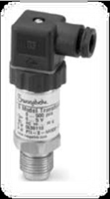
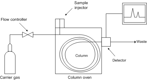
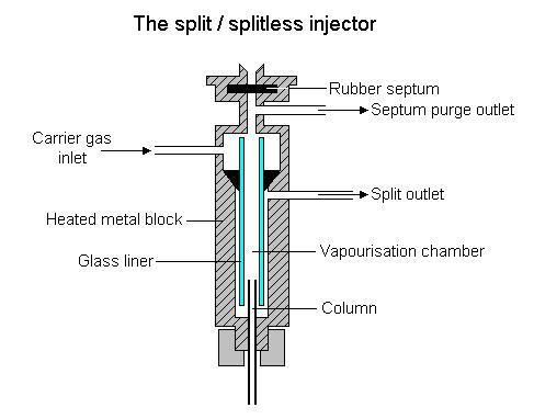
Multipurpose micro reactor and catalyst test setupInterlock descriptionIn order to prevention of undesirable state in the system, the interlock logic has been accomplished to provide ahigh level safety for the device and operator by stopping the system when tripped. The temperatures of all theheaters and pre-heaters can be set at two level point of high and high-high temperature. If the operating conditionsexceed the high temperature set-point at any reason, the alarm system warns and if the problem doesn't resolve,the emergency shut down is activated and electricity of the system except the PLC control panel and HMI shut offautomatic. All the pre-heater temperatures are adjustable at range of 0 to 500 °C. Also, the temperature interlock isemployed in each pump in order to safety of reactors and catalysts so that the pumps will not start as long as thepre-heater temperature reaches the given set point.This setup is also equipped with pressure transmitter and BPR ( figure 5) for control of system and the flash drumpressures. The pressure set point for PTs is visible and definable at the levels of high pressure, high-high pressureand low pressure which provides a high pressure security by a precise PID control loop. A high- high pressureinterlock turns off the pump and heaters and opens the related BPR when ESD alarm is activated. The BPRs of theDME synthesissection are operated at pressure range of 0-25 bar and those of the propylene synthesis section are programmedfor pressures of 0-10 bar. Since the BPRs show forward pressure, according to the intended BPRs as illustrated inappendix A, BPR parallel reactor (I) from PT -111, BPR parallel reactor (II) from PT-121 and BPR parallel reactor(III) from PT-131 receive the system commands. Also in the propylene synthesis section, BPR 170 from PT-170 andBPR 250 from PT-230 accept the commands.Figure 5. Pressure transmitter & BPR which are applied in this deviceIn addition, all the flash tanks, feed and water storage tanks are provided with level sensors and motor valves. Thelevel interlocks are programmed to commit the motor valves at high or low level condition. Based on this design,level sensors send the commands to open the motor valves at high level alarm and close them at a specified time orlow level condition.Since the drums No.170 and 250 are equipped with level transmitter (LT), hence opening and closing of the motorvalves manage based on the set point. Furthermore, there are the low level interlocks between the feed and waterstorages with the related pumps. Once the water or feed level reduces below the limit value, the PLC sends a shutdown command to the related pumps.Start up and operating procedureIn present work, in order to investigation of effective operating parameters in DME manufacture, a seriesexperiments were carried out in first section of the setup (DME synthesis section). At first, a calibration protocol forsensors that require calibration was developed. A lubricant pump is provided with a mixture of 80 percent by volumeof HPLC grade water and 20 percent by volume of isopropyl alcohol. In order to start up of the pumps, they areprimed by a flooded suction, the suction valves are opened and the liquid is allowed to flow into the pump. Also anair release valve is opened at the highest point in the pump casing to ensure that all the air/vapor is bled from thepump as it fills with the pumpage. Also, the feed, water and lubricant storage tanks are filled.The setup is connected to the power source and all the fuses are switched on from the heater and power controlstation. The electricity power of the PLC control panel is provided by turning on the UPS. Then, HMI is switched bythe operator key on the control desk and user can be accessed to the system by entering the password. It should bechecked the valves and flow meters be at the desired status. For the present work, since the parallel reactor II andits equipments are operated in the system, it is only required to close valve -120 in order to connection of effluentline to the GC. Next, the refrigeration system is started after checking up the heat exchangers. All the temperatureand pressure and level set points are set via HMI and until the operating parameters reach the set points, theamount of catalyst required is weighted and loaded into the parallel reactor II. The heat tracing temperatures arealso set at desired value by the heat tracing control panel. When the pre-heater temperature reaches theset point, the pump turns on and is set at the required flow rate.Gas chromatographyA gas chromatograph is a chemical analysis instrument for separating chemicals in a complex sample. It providesboth qualitative and quantitative information for individual compounds present in a sample. The gas chromatographmakes it possible to separate the volatile components of a very small sample and to determine the amount of eachcomponent present. The essentials required for the method are an injection port through which samples are loaded,a "column" on which the components are separated, a regulated flow of a carrier gas (often helium) which carriesthe sample through the instrument, a detector, and a data processor. In gas chromatography, the temperature of theinjection port, column, and detector are controlled by thermostatted heaters. Different chemical constituents of asample pass in a gas stream (carrier gas, mobile phase) at different rates which depend on their various chemicaland physical properties and their interaction with a specific column filling (called the stationary phase). As thechemicals exit the end of the column, they are detected and identified electronically. The function of the stationaryphase in the column separates different components, causing each one to exit the column at a different time(retention time). Other parameters that can be used to alter the order or time of retention are the carrier gas flowrate, and the temperature. A schematic diagram of the GC apparatus has been illustrated in figure 6. Figure 6. The schematic diagram f gas chromatographyInstrumental components Gas supply and carrier gasThe carrier gas serves as the mobile phase that moves the sample through the column. It must be chemically inert.The carrier gas system also contains a molecular sieve to remove water and other impurities. Commonly usedgases include nitrogen, helium, argon, and carbon dioxide. The choice of carrier gas is often dependent upon thetype of detector which is used.In this study, with regard to type of the detector (FID), availability and safety, helium is applied as carrier gas in theGC system. Sample injection portThe column inlet (or injector) provides the means to introduce a sample into a continuous flow of carrier gas. Theinlet is a piece of hardware attached to the column head. The temperature of the injector is controlled so that allcomponents in the sample will be vaporized and for optimum column efficiency, the sample should be injected in sosmall amount. The column inlets have different types. In this device two type of the "S/SL (Split/Splitless) injector"for manual injection via a syringe and "gas sampling valve" in order to automate injection of very small amount ofgas products. The S/SL injector is a hollow, heated, glass-lined cylinder where the sample is injected through theseptum (figure 7). The injector can be used in one of two modes; split or splitless. For present investigation, it wasset at temperature of 240 .C and splitless method was used under split flow of 0.8 ml/min and split ratio of 1/30.Figure 7. The split /splitless injectorReferences:•Mohadese Nazari, Determining Optimum Operating Condition of DME Production via Dehydration of Methanol over Acidic GammaAlumina Catalyst., M. Sc. Thesis, Petroleum University of Technology .,January 2011.•Omid Rahmanpour, Enhancement of the stability of Gamma Alumina catalyst using Multi Wall Carbon Nano Tubes (MWCNTs) as asupport for methanol dehydration., M. Sc. Thesis, Petroleum University of Technology .,2012.•Gas chromatography, 2008:< http://www.chromatography-online.org/topics/gas/chromatography.html>•Gas chromatography, Sheffield Hallam University, online learning:< http://teaching.shu.ac.uk/hwb/chemistry/tutorials>

 © Copyright 2013


 Chemical Engineering & Gas Processing


 Multipurpose micro reactor and catalyst test setup
Interlock description
Multipurpose micro reactor and catalyst test setup
Interlock description In order to prevention of undesirable state in the system, the interlock logic has been accomplished to provide a