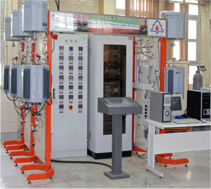
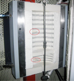
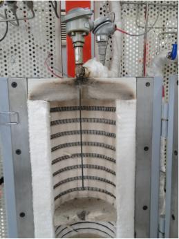
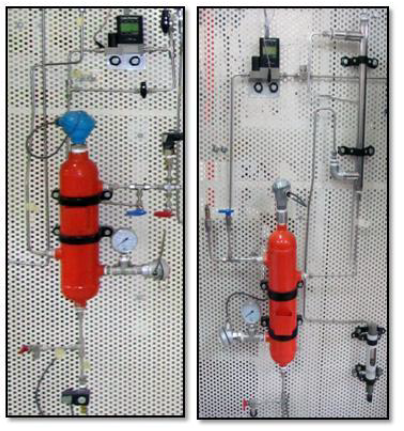
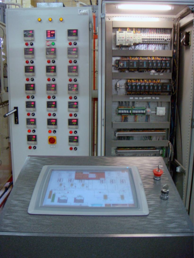
Multipurpose micro reactor and catalyst test setup for DME productionThis system is a multi purpose reactor comprising a refrigeration system, steam generator and six adiabatic fixed bed micro reactors which are equipped with a pre-heater, temperature and pressure controller. This system hasbeen designed so that the connection of the input and output reactors with gas chromatography is possible tomeasure the concentration of materials at any location of the device. In general, three of these reactors are inparallel which considered in order to DME synthesis from methanol and three series reactors has been embodied atthe other side of device to produce propylene from DME during the catalytic reaction.Each reactor has an individual preheater in order to heating and phase change of methanol feed. For each of theDME synthesis reactors, The HPLC pump has been employed to supply the liquid feed at the suitable flow rate.They control the outlet pressure and supply the feed with a high accuracy in lab scale range (0.01 ml per min). Then, DME as an intermediate is feed into the propylene synthesis reactors. The run status of the pumps isaccessible for operator on the screen of HMI (Human Machine Interface). The outlet of each pump is equipped witha pressure gauge and pressure safety valve. Since maximum temperature input to the pumps is equal 60 °C, thisequipments have been isolated by a check valve from the next section which operate at high temperature. Also, twopressure transmitters (PT) have been located at the inlet and outlet of the reactors to monitor the system pressureand maintain acceptable levels of safety. A pressure and high pressure set point are programmable for these instruments to active the high pressure alarm and ESD (Emergency Shut Down) in times of crisis. In addition, thesystem pressure is regulated by means of the back pressure regulators which are mounted on the vapor stream lineleaving the DME flash tanks. Figure 1 shows a general view of the setup.Figure 1. The schematic of experimental apparatusThe Pre-Heaters directly is connected to the 3/8” ID reactor via the traced Stainless Steel tube. The temperature of bed catalyst in each reactor has been measured by a submerged thermocouple which is placed in middle of thecatalyst bed. Furthermore, two thermocouples have been located at different positions in the shell to control and fixthe ambient temperature of the reactor. The thermocouples are connected to the microprocessor based thermoregulator. Also, as the temperature of each of the pre-heaters can be adjusted on the heater control station theactual steam temperature is also monitored by thermocouple on the HMI. The outer shell of the reactor is insulatedby glass wool layer to reduce heat losses and divided into two zones: a high temperature zone (Zone I) whichtubular reactor is placed and a low temperature (LT) zone (zone II) which is downstream of the HT zone to maintainalmost zero temperature gradient in the shell. The shell is covered by the heating elements which enables localheating of the reactor surrounding and provides better temperature control of the reaction zone. The temperaturesof zones are adjustable and visible on the heater control panel. Under this condition, an ideal adiabatic condition isprovided within the catalyst bed. A schematic of adiabatic fixed bed reactor is depicted in the figure 2.Figure 2. Adiabatic fixed bed reactor schematicFor temperature maintenance of the lines and prevention of the possible methanol and water condensation, theeffluent gases were heated by means of the electric heat tracing system. The heating tapes has been mounted on V the stainless steel tubes and covered with thermal insulation to retain heat losses from the pipe. The temperature isset by the heat tracing control panel and heat generated maintains the temperature of the pipe. The outlet productsfrom each of parallel reactor containing DME, water and unreacted methanol are passed through a shell and tubeheat exchanger to cool down to the ambient temperature. Cooled products are sent to a gas–liquid separator anddimethyl ether as a gas phase is transferred to the propylene synthesis reactors from top of the flash drums. Thepressure of the separator is also regulated and controlled by the back pressure regulator and are safe with PSV.These drums are equipped with a point-level sensor (LS) and motor valve to maintain the vessels at a safety level.Also, the temperature and pressure of the tanks are measurable by means of the temperature transmitter andpressure gauge. The final reaction effluent stream containing a greater amount of propylene from the serial reactor3 are supplied to the drum No.250. In addition, a flash drum (drum No.170) has been considered forthermodynamical investigations with a total volume of 1.565 liter. It is possible that the products stream of parallelreactor II be transferred directly to the drum by opening valve No. 102 and closing valve No.170. The two vesselsare equipped with the level transmitters which provide a precision level measurement for a wide variety. All thepressures, temperatures and levels of the drums are visible on the HMI. Figure 3 shows the both type of describedflash drums. Figure 3. The photograph of flash drums and their equipmentsAs was stated, this device has been termed a programmable automation controller PLC to establish a safe andreliable operating condition. In this control system, a programmable computer receives input signals from theequipment, processes this information using the structure and rules entered into the program and then it controlsoutputs that operate equipment. The PLC and the safety system check the process interlock which can informoperator at bad condition or in the emergency state automatically by activating the ESD (Emergency Shut Down).All control and measuring commands are sent and received with Analog (4-20 mA) or digital signal and areprocessed with PLC System. The measuring value such as all temperatures, pressures, feed flow rate, Productlevel, Run/Stop of the Pump and other control parameters are shown on the HMI.Figure 4. Heater control station, PLC controlTwo control panels have been provided for this system (fig.4). By means of the power and heater control station, thetemperature of heaters and pre-heaters are controllable with a precise PID control loop. This panel is comprised of19 controllers with a major key of electricity supplier and electrical fuses of equipments and SSRs (Solid StateRelay). The PLC control panel includes the instruments and PLC modules to handle multiple inputs and outputcommands of the system. Also, a UPS (uninterruptible power supply) has been considered to provide emergencypower for PLC control panel in case of an electrical failure.

 © Copyright 2013


 Chemical Engineering & Gas Processing


 Multipurpose micro reactor and catalyst test setup for DME production
This system is a multi purpose reactor comprising a refrigeration system, steam generator and six adiabatic fixed
Multipurpose micro reactor and catalyst test setup for DME production
This system is a multi purpose reactor comprising a refrigeration system, steam generator and six adiabatic fixed  bed micro reactors which are equipped with a pre-heater, temperature and pressure controller. This system has